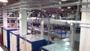
Stenter – mod. RAM/F
Technical Features
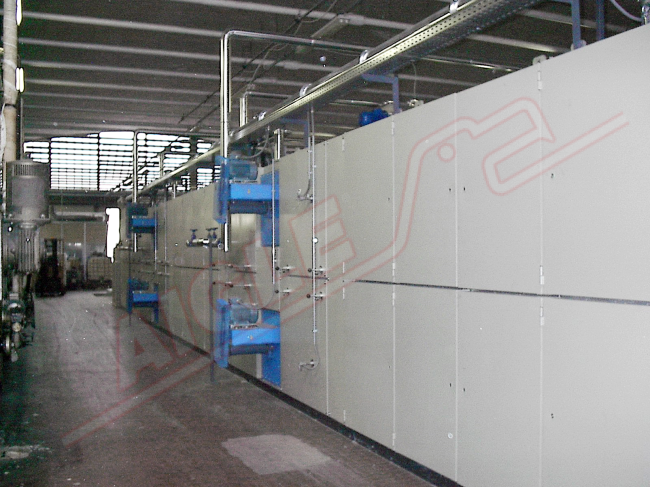
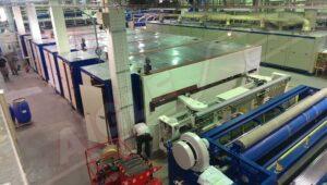
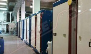
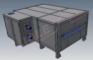
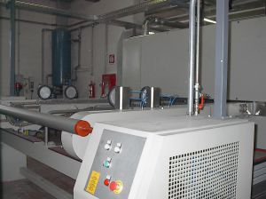
Stenter – mod. RAM/F
Features of the Stenter mod. RAM/F:
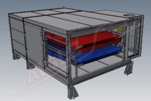
– Heating system; equipped with a circulation fan, a battery, oil related blowers, channel recovery and a filter. To ensure uniform heating and air distribution, the fields are opposing right/left. In order to reduce the electrical power consumption during the phase of the high temperature of the oven, all the recirculation fans are controlled with an inverter which regulate the speed as a function of temperature increases.
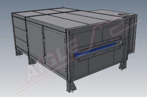
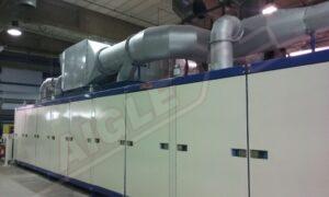
– Structure of the oven; side doors are placed along the sides with silicone rubber seals, to allow easy access inside.
Both the side doors and the top panels are made of galvanized steel containing mineral wool of high density. The oven is constructed to ensure maximum isolation.
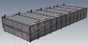
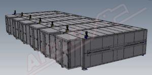
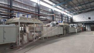
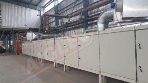
– Air exhaust system; consisting of exhausts located in the upper part of the furnace, connected with two air channels placed outside the furnace along the upper sides. For each field, variable openings are provided in order to obtain a perfect adjustment for the quantity of air aspirated locally. The stenter consists of a vertical chain system with pins equipped with automatic lubrication. The divergent field is controlled by two independent AC motors, equipped with inverter and activated by two sensors. Two pairs of rotating brushes pneumatically engage and drive forward the fabric. The correct chain tension of the stenter is automatically controlled by a pneumatic system. The rails of the stenter are divided into sections, one for each field. Each section is mounted on a motorized threaded transverse shaft that allows the variation of the width of the stenter to vary. The width of each field is controlled by encoders with PLC and displayed on the screen via the diagram.
– Thermo-Settings mod. TR; the temperature control system (one for each battery) consisting of:
- Modular three-way valve to command the tire, equipped with an electro/pneumatic transducer
- Temperature detector PT 100
- PID electronic control with digital display
– Electrical panel & PLC; the components of the engine are grouped on modular control panels. The main functions are displayed on the screen. Synchronization with the rest of the line is made via AC motors controlled by an inverter with vector function. The general synchronization of the system is obtained by an input signal to the tabs in charge of the control of the inverters. The general adjustment of the speed is effected via the motor potentiometer and signal amplifier. Electronic boards regulating the inverters are also equipped with potentiometers (corrected by percentage).
Technical data